
Threads are small features with big consequences. Whether you're designing a medical device housing or a structural aerospace bracket, threads play a critical role in assembly, serviceability, and performance.
But when threads aren’t designed with machining in mind, they can become a source of delays, cost overruns, and quality issues. Poor tool access, unclear tolerances, or non-standard specs can all lead to rework, hidden costs, and high scrap rates.
This guide is here to help you avoid those pitfalls. We’ll walk through what considerations you should take into account when designing threads that are easy to machine, inspect, and assemble (without compromising function), as well as some machining considerations, which could affect how you either produce the component in-house or outsource it to a machining partner.
Design Considerations
The Thread
Internal or external, profile, pitch, right- or left-handed thread, number of thread starts, and tolerance.
The first step in designing a thread for CNC machining is to determine whether the thread will be internal or external, as this influences both tooling and accessibility. While basic, this distinction is essential: external threads are found on fasteners like screws and bolts—protruding from the hardware—while internal threads are machined into components and serve to receive and secure those fasteners.


Choose a standard thread profile like metric or UN to streamline programming and inspection. Define the pitch and thread direction (right- or left-handed) to avoid ambiguity on the shop floor.
If the design calls for multiple starts, note that clearly in the engineering drawing, as it impacts both strength and cycle time. Finally, lock in your tolerances—both profile and positional—so machinists know exactly what’s acceptable and inspectors know what to measure.
The Component
Fixturing, chip evacuation and breakage, batch size, single or multi-thread.
Once thread features are defined, shift your focus to the component itself. Is it designed so that it be clamped securely for machining? If chip control is a concern, consider how the material behaves—some alloys break chips cleanly, others don’t.
You should also consider part volumes. For high-volume production, multi-tooth inserts or custom tooling could dramatically boost throughput, which would justify the increased tooling costs. But if you’re only planning to make or order lower volumes, custom tooling will increase your per unit cost without justifying the cost.
And if the part requires multi-start threads, flag that early—it affects both programming and tool selection. Every detail here influences cycle time, tool life, and part quality.
Thread Form
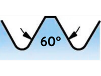
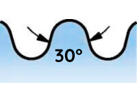
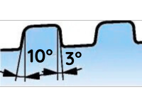
The thread profile determines the precise geometry of the thread, encompassing key dimensions such as major, pitch, and minor diameters, as well as the profile angle, thread pitch, and helix angle.
Note the most common thread forms and types in the table below.
| Thread Form | Thread Types | Application |
 |
ISO metric, American UN |
General threads |
 |
Whitworth, British Standard (BSPT), American National, Pipe Threads, NPT, NPTF |
Pipe threads |
 |
Round DIN 4005 |
Food and fire |
 |
MJ, UNJ |
Aerospace |
|
|
API Rounded, API “V” form 60°
API Butress, VAM |
Oil and gas |
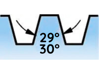 |
Trapezoidal/DIN 103, ACME, Stub ACME |
Motion threads |

Machining Considerations
The Machine
When designing threaded components, don't overlook the capabilities and limitations of the machine that will produce them. For example, larger thread diameters require machines with high stability, power, and torque to maintain accuracy and prevent tool deflection.
Engineers should also account for the number of available tool positions, as this affects whether the machine can accommodate the chosen threading method without compromising other operations. RPM limitations, particularly in bar-fed setups or when machining small diameters, can also restrict threading speeds and impact surface finish. Fixturing options like sub-spindles or tailstocks enhance support and concentricity, especially for long or slender parts.
Lastly, verify that the machine supports the required threading cycles—some advanced cycles can reduce cycle time and improve thread quality, but they may not be available on older or less capable equipment.
Chip Evacuation
Poor chip evacuation can lead to a range of issues, including tool breakage, poor surface finish, dimensional inaccuracies, and even scrapped parts. This is especially problematic in blind holes or deep threads, where chips have limited space to escape, and if you're working with a material that's prone to making long, stringy chips (i.e., aluminum).
If chips pack into the thread form, they can cause re-cutting, increase heat, and damage both the tool and the part.
To avoid these issues, engineers should:
- Design blind holes with enough clearance at the bottom so chips can collect without interfering with operation
- Specify thread relief grooves where appropriate to give chips a place to go and reduce tool wear
- Choose materials with good chip-breaking properties or select cutting tools optimized for the material
- Avoid placing threads too close to shoulders or walls, which can restrict chip flow and tool access
- Consider interrupted operations (like thread milling) that naturally improve chip evacuation due to cutting geometry
By factoring in chip control during the design phase, engineers can dramatically improve thread quality, tool life, and overall machining efficiency.
Fixturing Options
Engineers should ensure the component can be securely clamped without obstructing tool access to the thread location—this is especially important for external threads or multi-start configurations.
For parts with multiple threads or complex geometries, consider whether the fixture allows for repositioning or multi-axis machining to avoid setup changes. Long or thin-walled components may require soft jaws, custom supports, or vibration-damping fixtures to maintain stability during threading.
The more stable and accessible the part is during machining, the better the thread quality and consistency.
Threading Methods
Understanding the most common thread machining methods—like tapping, thread turning, and thread milling—helps design and mechanical engineers make smarter decisions early in the design process. It ensures threads are not only functional but also manufacturable, reducing the risk of costly redesigns, tooling issues, or production delays.
When engineers align thread design with machining capabilities, they improve part quality, speed up production, and strengthen collaboration with manufacturing teams.
Thread Turning
Thread turning presents unique challenges, particularly in achieving optimal chip control, maximizing tool life, and maintaining consistent component quality. During this process, the tool gradually forms the thread through a series of incremental passes, protecting the insert’s nose radius from excessive load by reducing the cutting depth on each pass.
External thread turning typically places fewer demands on tooling than internal thread turning, and several approaches are available depending on the application. Key considerations for external thread turning include:
- Setting the feed rate to match the thread pitch
- Selecting an appropriate number of passes and incremental depths of cut
- Managing chip formation to prevent accumulation around the tool or component
- Minimizing vibration caused by overhang and slender geometries
- Ensuring precise tool alignment and center height
Internal thread turning is inherently more challenging. Efficient chip evacuation becomes even more critical—particularly in blind holes—as longer and more slender tools are often required. Consider the following for internal operations:
- Use pull threading (left-hand tools for right-hand threads, and vice versa) to assist chip evacuation, while being mindful of potential insert movement
- Employ modified flank infeed to create a spiral chip that can be efficiently guided out of the bore
- Select proper pass counts and cutting depths to optimize accuracy and tool life
- Mitigate vibration by minimizing tool overhang or, if necessary, use carbide or damped tools for extended reach
- Maintain accurate tool alignment and center height
Careful planning for these variables will help you achieve more reliable, high-quality threads—regardless of whether the application requires external or internal threading.
Thread Milling
Thread milling creates threads by moving a rotating tool in a precise circular ramping motion. With each revolution, the tool’s lateral movement determines the thread pitch.
While thread milling is less common than thread turning, it delivers notable advantages for specific applications. This method should be prioritized when:
- Machining asymmetric or non-rotating parts
- Working with materials prone to chip control or evacuation issues
- Machining tough materials with high cutting forces
- Cutting threads near a shoulder or at the bottom of a blind hole
- Producing threads in thin-walled components
- Handling unstable or challenging setups
- Minimizing tool inventory is important
- Avoiding tap breakage in high-value parts, since thread mills can be withdrawn without damage
- The machine is capable of simultaneous X-, Y-, and Z-axis movement
Selecting thread milling in these scenarios optimizes reliability, tool life, and component quality.
Tapping
Tapping is a widely used and highly effective method for creating threads. This process delivers efficient and cost-effective threading—particularly for smaller thread sizes—thanks to minimized machine downtime, elevated cutting speeds, and extended tool life. Both forming taps and cutting taps are available in various designs, each tailored to specific requirements.
The material, coating, and geometry of every tap are critical to its performance and should be carefully matched to the intended application. A tap optimized for one material or operational context may yield suboptimal results in another.
Tapping accommodates a broad range of thread profiles and can be implemented across all machine types, supporting both rotating and stationary components.
Final Thoughts
When engineers understand how thread geometry, component features, and machining methods interact, they can design parts that are easier to produce, more consistent in quality, and less prone to delays.
This guide has walked through the critical considerations—from thread type and pitch to chip evacuation and fixturing—so you can anticipate manufacturing challenges before they impact production.
Whether you're working with high-volume production or prototyping a complex assembly, aligning your design with machining realities helps avoid rework, reduce costs, and improve collaboration with your manufacturing partners. Threads may be small, but when designed with intention, they deliver big results.


