
For many OEMs, especially those who are in the prototype phase of a product launch, in-house machining is a great way to reduce costs, quickly address engineering changes, and efficiently produce small batch runs – and tooling decisions play a big role in your machining capabilities and related costs.
If you’re in the market for CNC drills, you’ve likely noticed how expansive the tooling market is; there are countless tool manufacturers and a wide variety of drill features to consider.
Assuming you don’t want to blow through your team’s tooling budget or wind up with a bloated toolkit, consider these key factors when choosing a drill for your machining project:
- Workpiece material
- Size and depth of your hole
- Machine’s capabilities
These considerations will inform how you make material, coating, and geometry decisions when selecting your drill.
Drill Materials
Your choices in material and coating will play a critical role in your drilling operation. Selecting the right material-coating combo will extend your drill’s tool life and impact the quality of your parts.
High-Speed Steel (HSS)
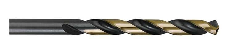
High-speed steel (HSS) is known for its high hardness and toughness. While maintaining a rigid setup is important, HSS excels when a rigid setup isn’t possible and there is potential for excessive tool holder overhang. Its toughness makes it less prone to brittle fracture or chipping compared to cobalt and solid carbide.
These tools are suitable for various ferrous materials like steel and iron, and non-ferrous materials such as brass, copper, and aluminum alloys, but should not be used in their hardened forms. However, HSS requires slower cutting speeds than cobalt or solid carbide, making it less ideal for high-production runs.
Cobalt
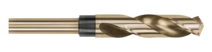
Cobalt steel drills are more wear and heat-resistant than HSS, offering longer tool life and faster operation. They serve as an intermediate option between high-speed steel and solid carbide. Cobalt drills can handle faster speeds than high-speed steel and are suitable for hardened and abrasive materials like bronze, stainless steel, cast iron, and titanium.
However, they don't retain edge sharpness as long as solid carbide and are more prone to brittle failure in non-rigid setups. While more expensive than high-speed steel, cobalt is a more economical choice than solid carbide. They perform well on both hard and soft materials.
Carbide
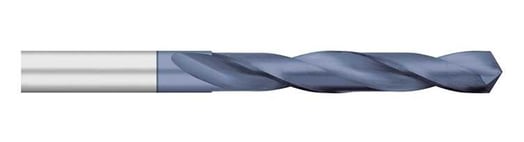
Solid carbide is the top choice for cutting tools due to its sharp edges, enabling the fastest operation among substrates. Despite being the most expensive, its ability to run at high speeds reduces cutting time, making it economical for high-production jobs. It offers excellent heat and wear resistance, extending tool life.
Solid carbide is ideal for hardened materials and high-temperature alloys, such as hardened steels, titanium, and nickel alloys up to 45RC, and with specific geometries and coatings, up to 68Rc. However, its high hardness makes it prone to brittle failure in non-rigid setups, leading to chipping or breaking during interrupted cuts, vibrations, or shocks.
Drill Coatings
Drill coatings not only enhance tool life, reduce friction, and improve heat resistance, but they also impact hole accuracy, surface finish, and machining costs. Conversely, drills can also have a Bright Finish, which is a coating-free drill that’s been polished.
Please note
The information below is intended to serve as general guidelines and should be used for research purposes. You should always contact the manufacturer about a particular for specs and safety data sheets.
Titanium Nitride (TiN)
General purpose coating with proven performance and increasing tool productivity with higher feeds and speeds in the machining of ferrous materials and in applications that are not generating excessive heat.
- Increased hardness
- Reduced friction and heat build-up
- Extended tool life
- Versatility
|
Materials |
General purpose; ferrous and non-ferrous |
|
Maximum working temperature |
1,000° F |
|
Hardness |
2170 (21 GPa) |
|
Coefficient of friction |
.40 - .50 |
Titanium Carbonitride (TiCN)
Maintains high surface hardness and increases abrasion wear resistance to improve overall tool life in lower-temperature applications. It also performs well across tough and abrasive workpiece materials.
- Low coefficient of friction
- Very high hardness
- Good lubricity
|
Materials |
Ferrous materials; stainless steels and other materials where AlTiN can’t be used |
|
Maximum working temperature |
750° F |
|
Hardness |
3,500 (34 GPa) |
|
Coefficient of friction |
.25 |
Aluminum Titanium Nitride (AlTiN)
This high-performance coating is well-suited for work on ferrous materials. It maintains its high surface hardness at elevated temperatures, which greatly improves tool life and allows for faster feed rates.
- Heat, wear, and oxidation resistance
- Promotes tool life
- High-performance, versatile coating
- Excellent for dry-machining
|
Materials |
Alloy steels, stainless steels, tool steels, Inconel, titanium, nickel-based alloys, and cast iron |
|
Maximum working temperature |
1,400° F |
|
Hardness |
3569 (35 GPa) |
|
Coefficient of friction |
.60 |
Zirconium Nitride (ZrN)
A less expensive alternative to diamond coatings, ZrN-coated drills are known for their high hardness, lubricity, and abrasion resistance.
- Can handle higher speed and feed rates
- Increased tool life
- Excellent corrosion resistance
- Improved chip evacuation
|
Materials |
Abrasive non-ferrous alloys like brass, bronze, copper and aluminum |
|
Maximum working temperature |
1,100º F |
|
Hardness |
2460 (24 GPa) |
|
Coefficient of friction |
.40 - .50 |
Drill Geometries
CNC drills are designed with a variety of geometries and features to enhance both performance and tool life. To optimize performance and tool life, you need to choose your drill's geometry based on the application at hand.
A solid understanding of CNC drill geometries will enable you to select the tool that’s best suited for your project.
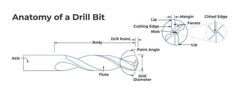
Point Angle
The point angle refers to the angle formed between the cutting edges of a drill bit at its tip. It plays a crucial role in determining the drill's cutting performance, penetration efficiency, and chip formation.
|
Common Point Angles |
Purpose |
|
118° & 120° Point Angle |
Standard for general-purpose drilling in softer materials like mild steel, aluminum, and plastics. |
|
135° Point Angle |
Used for harder materials like stainless steel and tougher metals; reduces thrust force and enhances tool life. |
|
140° Point Angle |
Ideal for very hard materials, reduces wear, and improves hole quality. |
|
150° Point Angle |
Large angles are often used for spot drilling applications, but the optimal spot drill angle is determined by the size of the angle of the final drill being used. |
Chisel and Cutting Edges
The chisel edge is the small, non-cutting tip of the drill where the flutes meet. It doesn't cut but pushes material aside, creating resistance. A wider chisel edge increases thrust force, making drilling harder, while a narrower one, like in split-point drills, improves penetration and reduces walking.
Web thinning can mitigate the chisel edge's negative effects. The cutting edges, the sharp parts along the drill's point, remove material by shearing it into chips that travel up the flutes. The angle of these edges affects chip formation, cutting force, and tool life.
|
Feature |
Function |
|
Chisel Edge |
Pushes material aside, does not cut |
|
Cutting Edge |
Shears and removes material; forms chips |
Flutes
Flutes are the most distinctive aspects of a drill, characterized by deep grooves that aid in chip removal during drilling. They are crafted to work in harmony with the drill's point angle, chisel edge, and cutting edges.
Tools with more flutes have a larger core, enhancing strength but reducing flute depth, which can limit chip space and cause packing issues in heavy material removal.
Traditionally, 2-flute tools are used for softer materials like aluminum, allowing faster feed rates and higher material removal rates (MRR), while 4-flute tools are preferred for harder materials like steel, offering greater strength and productivity.
Advances in machining have led to the use of 3-flute tools for non-ferrous materials, improving productivity and chip evacuation. For ferrous materials, tools now feature up to 7 flutes, enhancing tool life, reducing wear, and increasing productivity. Material-specific tooling optimizes flute count and coatings for effective machining, boosting MRR and productivity across various ferrous materials.
Helix Angle
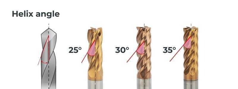
Helix angle refers to the angle of the drill bit’s flutes in relation to its axis. Similar to flutes, the helix angle is critical for chip evacuation, as well as cutting efficiency and hole quality.
Helix angle is important for chip control, cutting force, and tool life.
| Low Helix Angle (15° - 30°) |
Slower chip evacuation, producing smaller chips and reducing deflection; a more rigid ideal, which is ideal for harder materials like SS and titanium |
| Medium Helix Angle (30° - 40°) |
Commonly used for general-purpose drilling, due to its balanced performance; good chip evacuation and moderate cutting forces; suitable for a wide range of materials, like aluminum, mild steel and plastics |
| High Helix Angle (40° - 45°+) |
Fast chip removal, which can prevent clogging in softer or gummy materials; reduces heat buildup, which extends tool life; good for softer materials (aluminum, brass, copper) and deep-hole drilling |
Web
The web in a CNC drill bit refers to the central portion of the drill, running along its length, that connects the two flutes. It is the thickest part of the drill and provides structural strength.
A drill’s web design directly impacts durability, cutting efficiency, and chip flow.
- Stronger web improves tool breakage
- Thinner web improves cutting efficiency and reduces heat buildup on your cutting tool
- Optimized web improves chip flow and reduces the chance of tool failure
Corner Chamfer
Corner chamfer refers to the small, angled modification at a drill bit’s cutting edge (or hole entry/exit) to reduce burrs and enhance hole quality. Common chamfer angles include 30°, 45°, and 60°.
Drills with corner chamfers are often used to eliminate the sharp edge that emerges at the intersection of the flutes and ODs of a drill.
In addition to enhancing hole quality, reducing stress, and helping with fastener seating or part fitting, corner chamfers can also significantly extend tool life.
Drill Margin
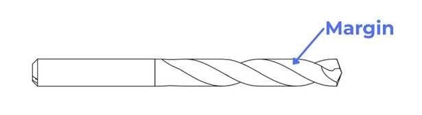
Drill margin refers to the narrow, raised cylindrical surfaces along the drill bit’s outer edges. These margins help guide the drill, maintain hole size accuracy, and reduce friction. A wide margin can enhance guidance but can increase friction and heat, resulting in faster tool wear.
The number of margins you need on a drill is typically determined by the type of hole being machined. Single-margin drills are frequently used for non-interrupted holes, while double or triple-margin drills are often employed for interrupted or intersecting holes.
More margins provide better guidance, helping the drill maintain a straight path through interrupted cuts, cross holes, and irregular or angled surfaces upon exit. However, while additional margins offer these advantages for irregular cuts, they also increase friction, leading to higher heat production. This accelerates wear and shortens the tool's lifespan.
Land
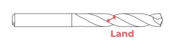
For CNC drills, land refers to the portion of the drill bit between the flutes where the cutting edges and margins are located. The area provides structural support to the drill bit and influences its cutting performance.
Land width determines how much torsional force a drill can take before failure. Smaller land means less torsional strength, but more chip space. Larger land allows for less chip space but provides more torsional strength.
Shank
The shank is the non-cutting end of the drill bit that is held by the tool holder, chuck, or collet of the CNC machine. It transmits rotational force (torque) from the spindle to the cutting edges of the drill.
There are several styles of shank to consider, including:
- Straight - a uniform cylindrical shape; commonly used in collets or chucks for general-purpose drilling
- Tapered - designed to fit into tapered holders; creates a secure self-locking system
- Reduced - smaller diameter compared to the drill body, allowing larger drill sizes to fit into standard chuck sizes
- Weldon - features a flat section for set screws, which prevents tool slippage in high-torque applications
- Hex - offers better grip in quick-change holders, which reduces tool slippage and improves torque transfer
If you have any questions or want feedback on how to select the right drill for your project, connect with one of our manufacturing engineers.


