Young’s modulus, E, is one of the first material properties mechanical engineers learn—and one of the most frequently oversimplified.
In design calculations, stiffness trade studies, and FEA material libraries, elastic modulus is treated as a fixed constant: a number you pull from a handbook, plug into an equation, and move on.
For many applications, that assumption is good enough. But for stiffness‑critical designs, thin‑wall components, precision assemblies, and machined parts that actually have to behave predictably in the real world, that simplification can introduce error.
Real metal parts are not pristine laboratory specimens. They are rolled, drawn, forged, heat treated, machined, unclamped, stress relieved, and sometimes distorted along the way. Each of those steps leaves behind a processing history that affects how the material responds elastically under load. The result is that the “E” value you design with is not always the “E” value your part exhibits in service.
This article explains how processing history alters elastic modulus in real metals, why engineers don’t notice it until something goes wrong, and how to think about elasticity in a way that better reflects how parts are actually made.
What Elastic Modulus actually Represents
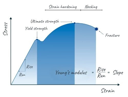
Young’s modulus is defined as the ratio of normal stress to elastic strain in the linear portion of the stress–strain curve:

In theory, elastic modulus reflects the stiffness of atomic bonds, which is why it is often described as a fundamental material constant. This framing explains why published values for E are typically presented as single numbers—around 69 GPa for aluminum alloys and roughly 200–210 GPa for steels.
That theoretical picture is not wrong, but it is incomplete. While atomic bonding sets the baseline stiffness, real elastic strain in metals is also influenced by microstructural behavior. Grain rotation, dislocation motion, residual stress relaxation, and crystallographic texture all contribute to how a material accommodates small, supposedly “elastic” strains.
In practice, the elastic region of the stress–strain curve is not perfectly linear, and it is not perfectly reversible.
How Processing History impacts a Metal's Microstructure
Every manufacturing process leaves a signature in the microstructure, and microstructure is the bridge between processing history and elastic behavior.
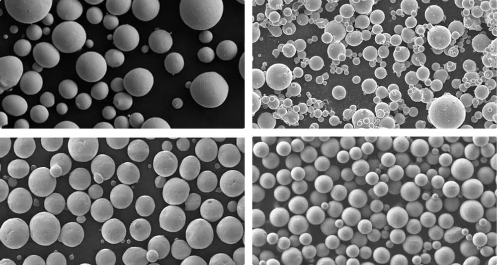
Rolling, drawing, forging, and extrusion elongate grains and introduce crystallographic texture. Cold work increases dislocation density. Heat treatment rearranges grains, relieves internal stresses, and can introduce or remove phases depending on the alloy.
Although these effects are often discussed in terms of strength or hardness, they also influence elastic response. Elastic deformation in metals is not purely atomic stretching; it is a collective response of the microstructure to load. When that microstructure is directional, stressed, or non‑uniform, elastic behavior becomes directional and history‑dependent.
Understanding elasticity, therefore, requires understanding how the metal arrived at its current state.
Fabrication Method
The route used to produce the starting material establishes the baseline elastic behavior. Fully annealed wrought material is generally the most isotropic and predictable.
Cold‑worked wrought products exhibit directional stiffness tied directly to processing direction. Cast metals introduce larger grain structures and, in some cases, porosity, both of which influence elastic response.
Additively manufactured metals represent an extreme case. Layer‑by‑layer construction creates strong anisotropy and residual stress gradients, meaning elastic modulus can differ significantly depending on build direction. Modeling additively manufactured parts with isotropic material properties often produces stiffness predictions that appear reasonable numerically but fail to match physical testing.
Cold Work
Cold working processes such as rolling, drawing, and forging plastically deform metal below its recrystallization temperature. Engineers correctly associate cold work with increased yield strength and hardness, but its influence on elastic behavior is often overlooked.
Cold work increases dislocation density and produces elongated grains aligned with the deformation direction. As a result, stiffness becomes directional. Measured elastic modulus along the rolling direction of cold‑worked plate can differ from the transverse direction by several percent, particularly in aluminum alloys and low‑carbon steels.
From a design perspective, this means that a rolled plate does not behave like an isotropic solid, even though it is usually modeled that way. A beam cut parallel to the rolling direction may deflect less than an identical beam cut transverse to it, despite both being made from the same alloy and nominal material condition.
This difference is rarely catastrophic, but in deflection‑limited designs or precision structures, it can be the difference between meeting requirements and chasing unexplained compliance.
Heat Treatment
Heat treatment modifies elastic behavior primarily by changing internal stress states and microstructural uniformity. Stress‑relief treatments, performed at relatively low temperatures, reduce residual stresses without significantly altering phases or strength. While the underlying atomic stiffness does not change, the material’s elastic response becomes more stable and repeatable because stored elastic energy is reduced.
Annealing goes further. By reducing dislocation density and allowing grains to recrystallize, annealing tends to bring elastic modulus values closer to published handbook numbers. This is one reason annealed wrought materials typically exhibit the most predictable elastic behavior.
In alloys where phase transformations occur—such as steels and titanium alloys—heat treatment can also change elastic modulus by altering the phase mixture itself. Ferrite, martensite, retained austenite, and α/β titanium phases do not share identical elastic properties. As a result, two parts with the same chemistry but different heat treatments can exhibit measurably different stiffness under load.
Machining and Elastic Recovery
Machining does not change atomic bonding, but it dramatically changes how elastic stresses are distributed. Removing material that was previously constraining residual stress causes elastic redistribution, which is why parts spring when unclamped and why thin‑wall components distort after roughing.
Near‑surface residual stresses introduced during machining also affect how a part elastically recovers after loading. Two parts with identical geometry and alloy, but different machining strategies or sequencing, can exhibit measurably different stiffness and dimensional stability once removed from the fixture.
This is why elastic problems so often appear after machining rather than during initial design.
Engineering Takeaways
When you evaluate both raw cost and machinability from the beginning, you reduce risk, improve quality, and avoid surprises once the part reaches production. The optimal material is rarely the cheapest—and rarely the strongest or hardest. It’s the one that delivers the required performance at the lowest total manufacturing cost.
The goal isn’t to avoid challenging materials altogether but to be deliberate in choosing them. When high performance is truly necessary—like in aerospace, medical, or high‑temperature environments—machinability challenges are expected. But in commercial or industrial applications where performance ranges are wider, selecting a moderately priced, highly machinable material often provides the best combination of quality, speed, and cost efficiency.
Engineers who treat material choice as a primary design variable rather than a late‑stage administrative detail tend to produce parts that are more manufacturable, more affordable, and more consistent in quality.
 Amanda White