
In aerospace and medical device manufacturing, precision isn’t optional. A single micron can separate a conforming part from scrap, and in industries governed by AS9100 or ISO 13485, that micron can mean the difference between compliance and catastrophic failure. Yet, the silent culprit behind dimensional drift often hides in plain sight: cutting tool wear.
Tool wear in CNC lathe operations occurs due to abrasion, thermal stress, and chemical diffusion, leading to flank wear, micro-chipping, and crater wear—all of which compromise dimensional accuracy.
Tool wear is inevitable. Every cutting edge, no matter how advanced, will degrade under the combined assault of heat, pressure, and friction. But what’s often overlooked is the cascading effect of this wear on tolerance stack-up, surface finish, and ultimately, product integrity.
For OEMs producing turbine shafts, orthopedic implants, or optical housings, the consequences of uncontrolled tool wear extend far beyond the shop floor—they ripple into regulatory audits, customer trust, and financial performance.
Understanding Tool Wear Mechanisms
Before we dissect individual wear modes, it’s important to understand why tool wear is such a persistent challenge in high-precision lathe operations.
Cutting tools operate in one of the harshest environments in manufacturing: extreme temperatures, high mechanical loads, and constant friction. Every second of contact between the tool and workpiece is a battle against physics—heat softens tool material, abrasive particles erode surfaces, and cyclic stresses initiate micro-fractures. For engineers working with aerospace alloys or medical-grade stainless steels, these conditions are amplified by material properties like low thermal conductivity and high hardness.
The complexity of tool wear lies in its multi-faceted nature. It’s not just a matter of time; it’s a function of cutting speed, feed rate, material composition, coolant strategy, and even machine rigidity.
Understanding the mechanisms behind tool wear is foundational for predicting tool life, maintaining dimensional accuracy, and preventing catastrophic failures. Each wear mode—flank wear, micro-chipping, crater wear—has distinct causes and consequences, and ignoring these nuances can lead to costly surprises on the shop floor.
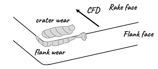
Flank Wear
Flank wear develops on the tool’s clearance face as abrasive particles in the workpiece—like carbides or silica—gradually erode the surface. This erosion increases cutting forces and heat, creating a feedback loop where rising temperatures accelerate wear. In challenging materials such as titanium, low thermal conductivity traps heat, causing flank wear to progress even faster.

Crater Wear
Crater wear develops on the tool’s rake face where the chip slides, caused by chemical diffusion and thermal stress at high temperatures. Atoms from the tool migrate into the chip, forming a concave crater and weakening the rake face. This is especially severe when machining nickel-based superalloys at cutting temperatures above 1,000°C. As crater wear progresses, it alters the rake angle, hampers chip flow, and raises cutting forces, often accelerating additional wear.
Micro-Chipping
Micro-chipping acts as a sudden disruptor in tool wear, causing localized fractures along the cutting edge from mechanical shocks or hard inclusions. Unlike the gradual nature of flank wear, micro-chipping is unpredictable—a tool may appear serviceable and then fail abruptly, producing out-of-tolerance parts without warning. In medical device machining, even small instances of micro-chipping can compromise part functionality and regulatory compliance.
Each wear mode changes the effective cutting geometry. A tool with flank wear loses clearance, increasing rubbing and heat. Micro-chipping introduces irregular cutting edges, producing erratic dimensional results. Crater wear modifies rake angles, affecting chip evacuation and surface finish. For parts with tolerances tighter than ±0.005 mm—common in aerospace and optical applications—these geometric shifts are unacceptable. The integrity of the cutting edge is the foundation of precision; when that foundation erodes, everything built upon it collapses.
The Domino Effect on Dimensional Accuracy
Precision machining is a game of control. Every variable—tool geometry, spindle speed, coolant pressure—must be orchestrated to produce parts within microns of tolerance. When tool wear enters the equation, that control begins to unravel.
The danger lies in the cumulative nature of these effects. A worn tool doesn’t just produce one bad part; it introduces systemic variability that propagates through batches, creating tolerance stack-ups that escape detection until final inspection. For aerospace OEMs, this means scrapping components worth thousands of dollars. For medical device manufacturers, it means risking regulatory non-conformance under ISO 13485—a scenario that can trigger audits, recalls, and reputational damage.
Tolerance Drift
As flank wear advances, the tool’s cutting diameter subtly shifts, leading to dimensional drift—often resulting in undersized or tapered features. In aerospace shaft turning, even a 0.01 mm deviation can cause parts to fall outside AS9100 standards. Such deviations can accumulate across multiple features, creating tolerance stack-up that often remains undetected until final inspection.
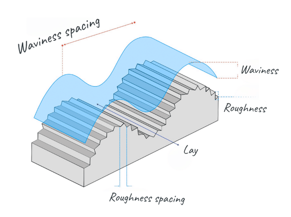
Surface Finish Degradation
Micro-chipping compromises surface integrity, leaving microscopic irregularities that act as stress concentrators. In aerospace applications, this can reduce fatigue life by up to 30%. For medical implants, poor surface finish impairs osseointegration and increases regulatory risks.
Compliance Risk
In regulated sectors, dimensional accuracy is a compliance requirement, not just a quality standard. Standards like ISO 13485 and AS9100 demand strict process control and traceability. A single nonconforming part can lead to audit findings, non-conformance reports, or costly recalls—consequences that far outweigh the price of any tool.
What starts as a barely perceptible change in edge geometry can snowball into dimensional drift, surface finish degradation, and compliance risks that threaten entire production runs. Understanding this domino effect is critical for engineers tasked with safeguarding precision in high-stakes industries.
Quantifying the Hidden Cost
When engineers think about tooling costs, they often focus on the price of inserts or cutters. But the real cost of tool wear is far less obvious. It hides in scrap bins, inspection queues, and missed delivery deadlines. A single worn tool can derail an entire production schedule, turning what should be a predictable process into a cascade of financial and operational setbacks.
The challenge is that these costs are rarely visible in isolation. Scrap and rework inflate material expenses, while extended cycle times choke throughput. Inspection bottlenecks strain quality departments, and delayed shipments erode customer trust.
Scrap and Rework
A $20 carbide insert can determine the fate of a $10,000 aerospace shaft: if it wears prematurely and causes an undersized feature, the entire shaft becomes scrap. When this happens across a batch of 50 parts, the financial losses climb rapidly. Often, rework isn’t possible—especially for components with critical surface or heat treatments—leaving scrapping as the only option.
Cycle Time Impact
Worn tools force operators to lower feeds and speeds, prioritizing tool life over productivity. For example, a lathe set for 500 mm/min may be reduced to 350 mm/min, increasing cycle times by up to 30%. In high-volume medical device production, such delays risk missed delivery deadlines and strained customer relationships.
Indirect Costs
Tool wear creates inspection slowdowns as more parts require dimensional checks, leading to missed delivery dates and potential penalties in aerospace contracts. Most critically, it can damage reputation and erode customer trust—an expense no metric can truly capture. For OEMs, reliability is essential; unchecked tool wear undermines that reliability instantly.
For OEMs operating under tight margins and strict compliance standards, these indirect costs can dwarf the price of any cutting tool. Quantifying this impact isn’t just an exercise in accounting—it’s a wake-up call for why proactive tool wear management is a strategic imperative.
Tool Wear Mitigation Strategies
If tool wear is inevitable, the question becomes: how do we control it?
The answer lies in shifting from reactive maintenance to proactive process optimization. Traditional approaches—waiting for visible wear or relying on operator intuition—are not sufficient in industries where tolerances are measured in microns and compliance failures carry million-dollar consequences.
Modern mitigation strategies combine advanced materials science, real-time monitoring, and digital simulation to transform tool wear from an unpredictable liability into a manageable variable. Predictive analytics powered by AI can forecast tool life with remarkable accuracy. Coatings engineered at the molecular level can withstand extreme thermal and mechanical loads. High-pressure coolant systems and digital twins offer unprecedented control over cutting conditions.
Predictive Monitoring
Reactive tool changes are now obsolete. Modern machining leverages in-process sensors and AI-driven analytics for real-time tool health monitoring. Acoustic sensors catch micro-chipping early, while vibration analysis reveals flank wear. Machine learning predicts tool life with ±5% accuracy, enabling proactive tool changes that prevent scrap.
Tool Material and Coatings
Advances in carbide grades and PVD coatings—such as TiAlN and AlCrN—have significantly improved tool performance, offering up to 40% longer tool life by reducing abrasion and thermal cracking. When machining demanding materials like titanium or Inconel, these coatings provide a thermal barrier that helps minimize crater wear and keeps cutting geometry stable under extreme conditions.
Coolant Optimization
High-pressure coolant systems target the cutting zone, reducing heat and efficiently clearing chips. This minimizes tool wear and edge damage, which is especially crucial in deep-hole turning and medical device machining, where surface finish and chip evacuation are critical to success.
Digital Twin Integration
Digital twins model tool wear under real-world cutting conditions, helping engineers optimize tool changes and machining settings. By capturing thermal loads, cutting forces, and material interactions, these simulations turn tool wear into a predictable, controllable factor—supporting AS9100’s focus on risk-based thinking for aerospace OEMs.
For engineers, these technologies aren’t optional—they’re the new baseline for competitive, compliant, and cost-effective manufacturing.
Tool wear isn’t just a maintenance issue—it’s a precision problem with cascading effects on cost, compliance, and performance. For OEMs in aerospace, medical, and industrial sectors, ignoring tool wear means gambling with tolerances, timelines, and reputation.
The solution lies in a proactive, data-driven approach: predictive monitoring, advanced tooling strategies, optimized coolant systems, and digital twin integration. These investments safeguard dimensional integrity, protect compliance, and keep high-value parts—and your bottom line—out of the scrap bin.
Don’t treat tool wear as an afterthought. Make it a strategic priority. Your parts, your customers, and your reputation depend on it.


