
CNC milling cutting parameters—speeds, feeds, and tool engagement—directly control heat, tool wear, and dimensional accuracy in machined parts. When design engineers understand the basics, they can specify features and tolerances that run at stable cutting conditions instead of forcing shops into slow, fragile toolpaths that drive cost and risk.
For OEMs in medical, aerospace, and biotech, that impact is concrete. Consider a 5‑axis aluminum housing with thin walls and tight positional tolerances between bores. If the geometry only allows tiny tools and shallow engagement, a part that could otherwise be roughed in 8 minutes at robust parameters might take 30 minutes or more to mill under those tooling constraints. Multiply that by hundreds of pieces, and you have schedule slip, higher unit cost, and more opportunity for scrap.
The good news: you don’t need to become a CAM programmer to address these problems that arise due to cutting parameters. You just need a working model of what your machinist is trying to achieve at the spindle. With that, you can spot red‑flag features, ask better questions, and adjust your design to achieve faster, safer cutting strategies—especially on complex 4‑ and 5‑axis work that could run lights-out if properly optimized.
In this article, we’ll focus on how cutting parameters and engagement interact, and what that means for material removal rate, surface finish, and tolerance control on the parts you design.
Cutting Parameters
Often shortened to “speeds and feeds,” cutting parameters are applied in every milling operation and must be tuned for each tool based on diameter, type of cut, and workpiece material.
Defining appropriate speeds and feeds before you begin machining is essential: they establish a baseline for a given tool that delivers reliable performance while protecting surface finish and extending tool life. Get the cutting parameters right for the material and tool, and everything is stable. Get it wrong, and you'll generate heat, chatter, and size problems.
Surface Speed
Cutting speed—also called surface speed—is the relative speed between the tool and the workpiece along the cutting surface, typically expressed as surface feet per minute (SFM).
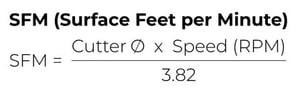
When the workpiece is fixed, SFM describes how fast the cutting edge travels across the part while in contact. In multi‑axis setups where both the tool and part are moving, SFM is based on the relative surface speed between them and must be calculated from that combined motion.
Spindle speed, measured in revolutions per minute (RPM), is then calculated from that SFM value and the cutting tool’s diameter. Because SFM is material-specific (recommended surface speed is driven primarily by the workpiece's material properties), it stays essentially constant for a given workpiece alloy, even as you adjust chip load or change the style of cut.

In imperial units, the standard constant 3.82 links surface speed, spindle speed, and cutter diameter. To solve for SFM, multiply the tool diameter (in inches) by the spindle speed (RPM), then divide by 3.82.
For example, a 0.5 in carbide end mill in 6061 aluminum might run around 800 SFM. That gives roughly 6,100 RPM. A reference sheet from a major cutter supplier shows practical SFM ranges for aluminum between ~600–1,000 SFM, while titanium often lives down around 200–350 SFM.
Feed Rate
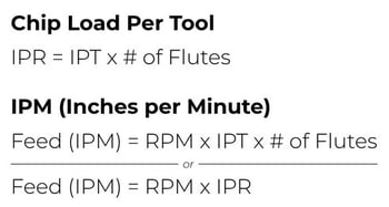
Feed rate is how fast the tool cuts through the material, measured in IPM (Inches per Minute).

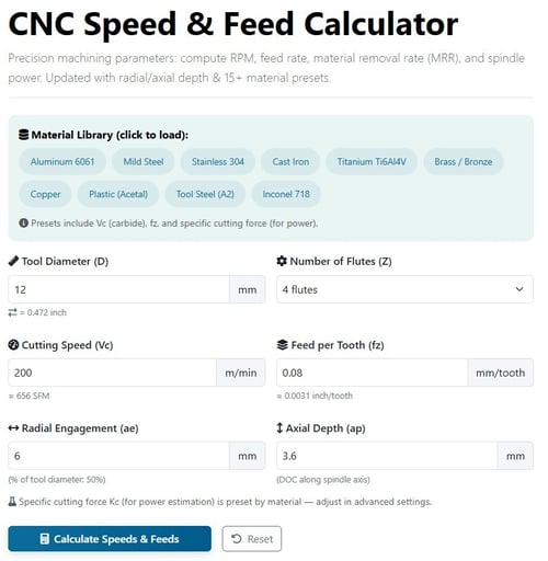
A free speed‑and‑feed calculator like GetZenQuery’s CNC calculator uses these same formulas. Plugging in a 12 mm, 3‑flute carbide tool in 6061 aluminum at 200 m/min with 0.08 mm/tooth shows a feed rate around 1,700 mm/min and a material removal rate (MRR) of about 2.2 in³/min at moderate engagement.
Chip Load
Chip load is the amount of material removed per revolution of your cutting tool. Chip load per tooth and chip load per tool are related but distinct, and it’s important to treat them separately:
Chip load per tooth is the thickness of material a single cutting edge removes in one revolution of the tool, typically specified in inches per tooth (IPT).
Chip load per tool is the total thickness of material removed by all cutting edges in one revolution of the cutter, expressed in inches per revolution (IPR).
A chip load that is too large can pack chips in the cutter, causing poor chip evacuation and eventual breakage. On the other hand, a chip load that is too small can cause rubbing, chatter, tool deflection, and a poor overall cutting action.
Finding the correct balance will not only allow for the most efficient cut possible, but also ensure the most efficiency in regard to tool wear. When calculating chip load per tool or or per tool, chip load is multiplied by the number of flutes on the tool itself.
Material Removal Rate
Material removal rate (MRR) isn’t a programmed input, but it’s a useful metric for comparing how efficiently a tool is cutting. MRR depends on two engagement parameters: axial depth of cut (ADOC), the length of the tool engaged along its centerline, and radial depth of cut (RDOC), the width of the stepover into the workpiece.
The MRR calculation (seen below) relies on the calculated feed rate. The feed rate (IPM) is multiplied by the radial and axial depths of cut to produce the rate of removal.
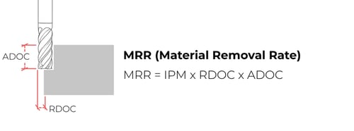
The tool’s depth of cuts and the rate at which it is cutting can be used to calculate how many cubic inches per minute (in3/min) are being removed from a workpiece.
This equation is extremely useful for comparing cutting tools and examining how cycle times can be improved. Decreased cycle times leads to higher productivity within a shop, which is what all machinists aim for during production.
Engagement
Speeds and feeds set how fast the tool moves. Radial engagement and axial depth of cut determine how much of the tool is working, where chips form, and how forces enter the part. Together, they define load, heat generation, and the risk of chatter.
Radial engagement (ae) is the width of the cut. Full‑slotting is 100% ae; light “constant‑engagement” roughing might use 5–20% of the diameter.
Axial engagement (ap) is depth along the tool. Pushing ap high while keeping ae low lets shops use more of the cutting edge length, improving tool life and reducing notch wear. A 10% ae, 2×D ap roughing pass with a 10 mm end mill can be both faster and gentler on the tool than a shallow, wide stepover.
For design engineers, the key is understanding how geometry constrains these knobs:
- Narrow slots near tall walls force higher ae at low ap, because the tool can’t step over without hitting adjacent surfaces.
- Deep pockets with small corner radii compel long, slender tools. Those tools can’t tolerate high ap without deflecting.
- Thin floors or walls limit both ap and ae because cutting forces must be kept low to avoid vibration.
A practical example: compare two pocket designs in 7075 aluminum.
|
Version A has 2×D depth with 1 mm internal radii driven by a compact PCB outline. Version A may demand a 2 mm end mill at 6×D reach with 5–10% radial engagement and very cautious ap. |
Version B relaxes corners to 3 mm and allows a small corner relief under a non‑critical cover. Version B can run a 6 mm tool at 0.5×D ap and 20–30% ae. |
The second case often cuts in less than half the time with better surface integrity.
Design Better Parts with Cutting Parameters in Mind
Every decision you make on wall thickness, corner geometry, and tolerances has a downstream effect on feasible cutting parameters. A few pattern‑level changes often unlock much better milling conditions without compromising function.
1. Use realistic fillet radii to allow larger tools.
Internal corners set maximum tool diameter.
|
Problem Choosing a 0.5 mm fillet instead of 2 mm forces much smaller tools, with lower SFM, lighter chip load, and more passes. |
Solution If a feature doesn’t truly need a tiny corner, increasing fillet radii is an easy way to improve machinability. |
2. Avoid unnecessary full‑width finishing passes.
When adjacent features are spaced too tightly—like ribs with slivers of material between them—you can force full‑slot cuts at final size.
|
Problem At 100% ae, where chip load spikes as the flute enters and exits material. |
Solution Slightly increasing gaps or combining ribs can create room for multi‑pass finishing at 30–50% ae with better control of chip thickness and deflection. |
3. Control wall heights and aspect ratios.
A thin wall 4× taller than its thickness is far harder to mill than one at 2×, even if both are well within structural limits.
|
Problem Tall, flexible walls force shallow ap and very light ae to keep vibration under control. |
Solution If the function allows, splitting a tall wall into two shorter steps or adding a non‑functional rib for stiffness can restore access to stable parameters. |
4. Match tolerances to what the process can hold naturally.
Modern VMCs with carbide tooling routinely hold ±0.001" on features cut in a single setup, especially when cutter compensation and dedicated finishing passes are used.
|
Problem Pushing to ±0.0005" across deep pockets or multi‑setup relationships may require slower finishing cuts, conditional inspection steps, and climate control. |
Solution The tighter your tolerances, the more you’re forcing conservative, low‑MRR parameter choices across the program. |
5. Leave machinable stock for finishing.
Roughing and finishing should use different cutting parameters.
|
Problem If the model or drawing demands “from solid” surfaces everywhere, shops lose that flexibility and either risk deflection or slow down the entire toolpath to protect final dimensions. |
Solution Leaving 0.2–0.5 mm of stock on walls and floors for a final light pass lets machinists tune speeds and feeds just for surface finish and accuracy. |
How to collaborate with your machining partner on parameters
Engineers don’t need to specify exact RPM or IPM on drawings, but the best results come when design intent and cutting strategy are discussed early. A brief conversation about speeds, feeds, and engagement can prevent weeks of iteration on a difficult part.
Start by sharing how the part will be used and which features drive function. For a medical pump housing, that might be the positional tolerance of fluid ports and sealing land flatness. Once those are clear, invite your machinist to propose tool sizes and engagement strategies for those areas. If they say, “To keep chip load stable, I really need a 6 mm tool here,” consider whether you can open up a corner or relax a pocket depth to allow it.
Second, be explicit on where you’re flexible. Call out where fillets may grow, where walls can thicken, or where tolerances can open from ±0.001 in to ±0.003 in. This gives programmers room to choose more aggressive parameters—higher SFM, higher chip load, and constant‑engagement paths—without guessing.
Finally, use data. Ask your machining partner what material removal rates they typically achieve in 6061, titanium, or 17‑4PH at your volume. If your feature set would force them down to a fraction of that baseline, you can make an informed decision: accept the cost and lead time, or adjust the design to support better cutting parameters.
Treat speeds, feeds, and engagement as shared constraints in your design reviews, not an invisible implementation detail left for the shop to figure out.

 Amanda White